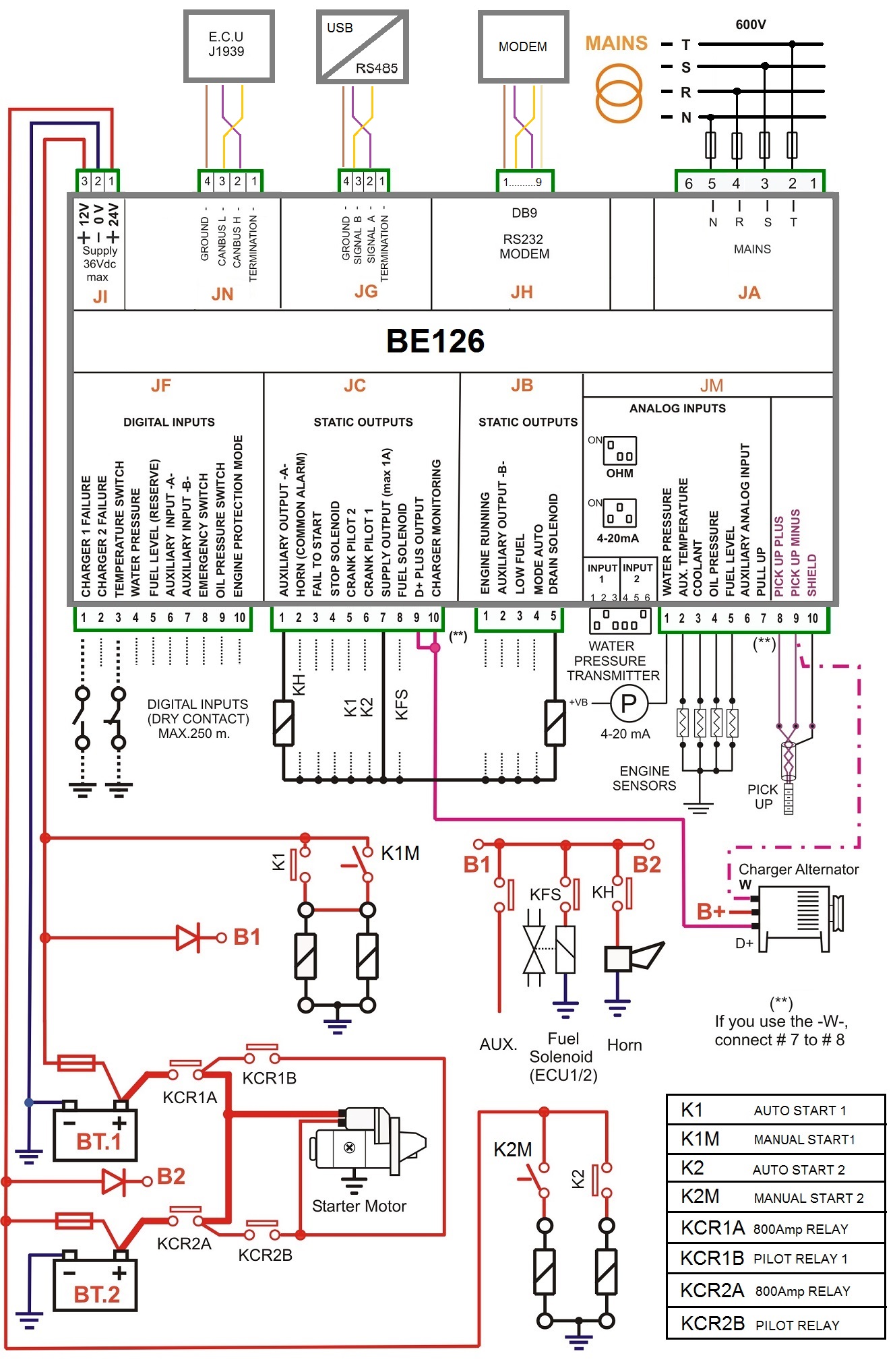
Find all Fire Pump Controller drawings as well as Jockey Pump Controller, Remote Alarm Panel, and Low Suction Shutdown Controller drawings here. FIRE PUMP CONTROLLER WIRING DIAGRAM. THIS IS THE RECOMMENDED BASIC WIRING DIAGRAM.

OPEN THE CONNECTION DESCRIPTION PAGE TO . XTJY Jockey Pump Controllers – Wye Delta (Star Delta). All enclosures finished in FirePump red. Diesel Engine Fire Pump Controllers.

Types of Diesel Engine Fire Pump Controllers. Terminal Strips Descriptions in the manual). Non-listed and ANPI-approved controllers for fire pump. When installing conduit for wiring, extra care should be taken to insure that metal .

LMR PLUS Electric Fire Pump Controllers. Connect the following wires to the fire pump engine digital control panel per the engine elec- trical diagrams. Mar 20- Figure 1: The fire pump connects to fire pump controller. The fire pump controller Electrically powered fire pumps are subject to many national . A part winding fire pump controller reduces the.
A fire pump is a part of a fire sprinkler system’s water supply and powered by electric, diesel or. The jockey pump is essentially a portion of the fire pump’s control system. A jockey pump is sized for a flow less than the flow to one sprinkler in . ALARM AND ENGINE WIRES ARE TO BE COPPER CONDUCTOR ONLY . Mark IIxg Electric Fire Pump Controllers.
Wye-Delta Open Transition Starting. I have a fire pump wired from controller. Reference engine wiring diagram and Field Connection Diagram FC1100. Field Simulation of Pump Controller Alarms. DC Jacket Water Heater Wiring Diagrams.
A typical Fire Pump installation is shown in Figure.